Menü
PLUTO PROJECT
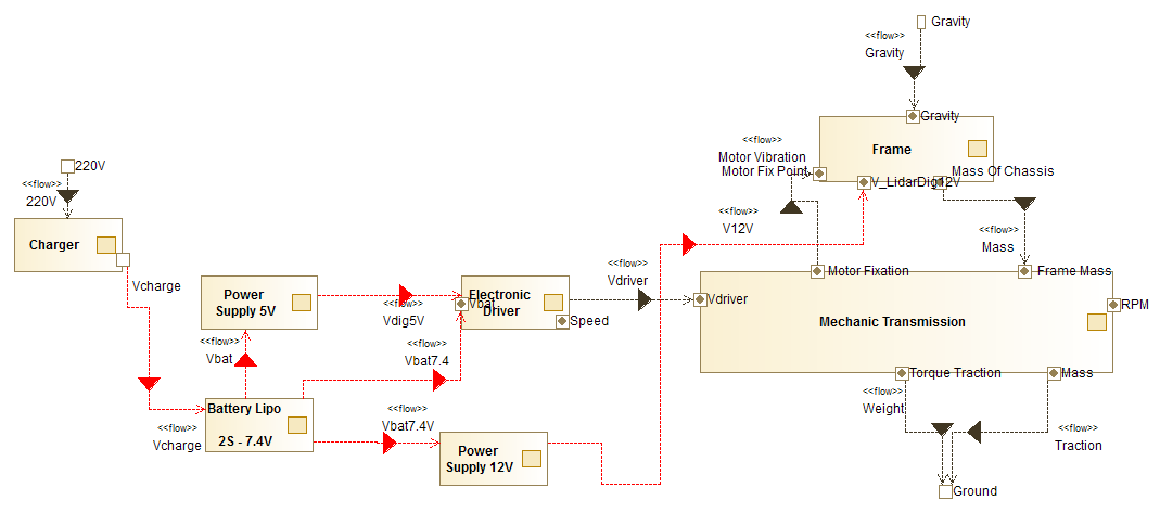
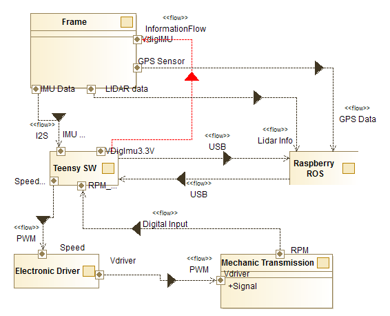
Electronic System Overview
Electronic system Design
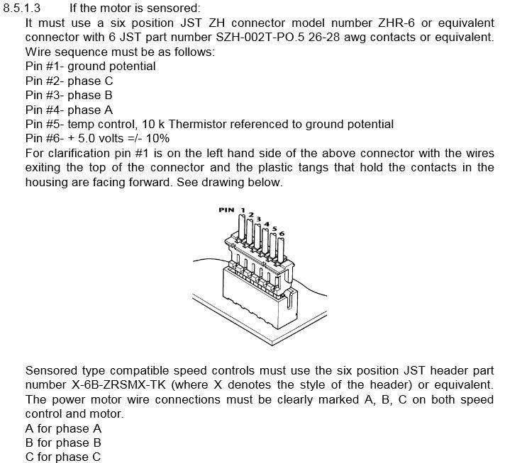
The base controller is strongly inherited from the linorobot Base Controller for the 2WD design. The DC motors in the original projects are substituted with Brush-less and ESC system (See system overview for more details)
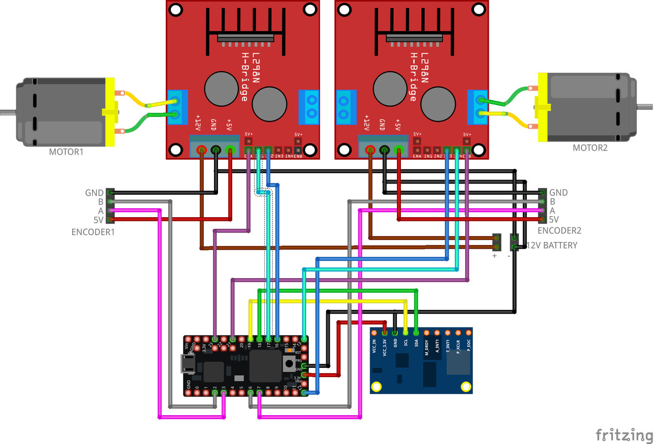
The above schematics is amended as follow:
Motor Controls
- Controller Motor Left define PWM PIN 21
- Controller Motor Right define PWM PIN 5
RPM Acquisition
NOTE: acquisition signals are split between ESC and Teensy
- Motor Left Phase_A 15
- Motor Left Phase_B 14
- Motor Left Phase_C 20
- Motor Right Phase_A 10
- Motor Right Phase_B 11
- Motor Right Phase_C 6
Electronic system interaction
The system interactions, between different components are defined as follow. (Powers flow and control flow)
Wir verwenden Cookies auf unserer Website, um Ihnen die relevanteste Erfahrung zu bieten, indem wir uns an Ihre Vorlieben erinnern und Besuche wiederholen. Durch Klicken auf "Akzeptieren" stimmen Sie der Verwendung ALLER Cookies zu.
Manage consent
Privacy Overview
This website uses cookies to improve your experience while you navigate through the website. Out of these, the cookies that are categorized as necessary are stored on your browser as they are essential for the working of basic functionalities of the website. We also use third-party cookies that help us analyze and understand how you use this website. These cookies will be stored in your browser only with your consent. You also have the option to opt-out of these cookies. But opting out of some of these cookies may affect your browsing experience.
Notwendige Cookies sind für die ordnungsgemäße Funktion der Website unbedingt erforderlich. Diese Cookies gewährleisten anonym grundlegende Funktionen und Sicherheitsmerkmale der Website.
| Cookie | Dauer | Beschreibung |
|---|---|---|
| cookielawinfo-checbox-analytics | 11 months | This cookie is set by GDPR Cookie Consent plugin. The cookie is used to store the user consent for the cookies in the category "Analytics". |
| cookielawinfo-checbox-functional | 11 months | The cookie is set by GDPR cookie consent to record the user consent for the cookies in the category "Functional". |
| cookielawinfo-checbox-others | 11 months | This cookie is set by GDPR Cookie Consent plugin. The cookie is used to store the user consent for the cookies in the category "Other. |
| cookielawinfo-checkbox-necessary | 11 months | This cookie is set by GDPR Cookie Consent plugin. The cookies is used to store the user consent for the cookies in the category "Necessary". |
| cookielawinfo-checkbox-performance | 11 months | This cookie is set by GDPR Cookie Consent plugin. The cookie is used to store the user consent for the cookies in the category "Performance". |
| viewed_cookie_policy | 11 months | The cookie is set by the GDPR Cookie Consent plugin and is used to store whether or not user has consented to the use of cookies. It does not store any personal data. |
Funktionale Cookies helfen dabei, bestimmte Funktionen auszuführen, z. B. den Inhalt der Website auf Social Media-Plattformen zu teilen, Feedbacks zu sammeln und andere Funktionen von Drittanbietern.
Leistungscookies werden verwendet, um die wichtigsten Leistungsindizes der Website zu verstehen und zu analysieren, um den Besuchern eine bessere Benutzererfahrung zu bieten.
Analytische Cookies werden verwendet, um zu verstehen, wie Besucher mit der Website interagieren. Diese Cookies liefern Informationen zu Metriken wie Besucherzahl, Absprungrate, Verkehrsquelle usw.
Werbe-Cookies werden verwendet, um Besuchern relevante Anzeigen und Marketingkampagnen bereitzustellen. Diese Cookies verfolgen Besucher auf verschiedenen Websites und sammeln Informationen, um angepasste Anzeigen bereitzustellen.
Andere nicht kategorisierte Cookies sind solche, die analysiert werden und noch nicht in eine Kategorie eingestuft wurden.